|
-2.jpg)
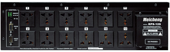
①EMG/EXT (DC 12V~24V): Emergency/External start control.
②REM IN (DC 5V) for IR remote control input
③RS-232 IN
④RS-232 OUT
⑤1~12 OUTLETS (Channel 1 ~12)
⑥Mains Connection Terminal
⑦Wiring Terminal Protective Shield
Operation:
1.
Mains connection
A. Use 2.5, 4.0, or 6.0 RV/RVV/BV/BVV
copper wires according to power
specifications.
Note: Properly connect in through
L(live), N(neutral) and Ground wire.
B.
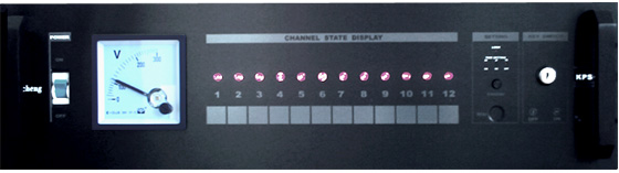
When the circuit breaker is on, voltmeter
indicates the AC voltage.
2.
Control Operation
A. Ensure “LOCK”
on the front panel lights off.
Press the
STANDBY key on front Panel, to turn on/off power. During the turning
on/off process, press STANDBY to finish
operation.
Note: “press”
in this operation means “press and hold the key for seconds”
(When the key is effectively on, there
is change in LOCK status).
B. Use 1-12 Channel
Control Key to control the power on/off of each channel
when “LOCK” is off.
C. Use Key
Switch to turn on/off power, independent of LOCK status.
Note: Remote Control can not control “LOCK” when Key Switch is on.
3.
Set-up Operation:
Use Remote Control to set up
the system after power is turned off and “LOCK” is lit.
A.
Set on/off BYPASS:
Set on any channel as BYPASS,
then the channel outlet being switched on. Equipments incorporating
clocks or timers such as MTC timer controller, VCR’s, or equipment
that must respond to wireless remote actuation should use the
outlets.
Sample
1:
Set on Channel 1 and Channel 2 as BYPASS.
Press Set on to light on. Press “1” key on, then press BY, and OK Indicator
lights up for 1 second, showing the setting is confirmed. Press
“2” key on, then press BY, and OK Indicator
lights up for 1 second, showing the setting is accomplished. Thus
Channel 1 and Channel 2 become BYPASS,
and both channels light up constantly.
Sample
2:
Set Channel 2 off BYPASS.
Press Set off to light on. Press “2” key, then press BY, channel 2 turn off,
and OK Indicator lights on for 1 second, showing the setting is
accomplished. Thus Channel 2 cancel BYPASS mode.
B.
Set the delay interval between adjacent channels of power up or
down:
The delay time is factory preset
as 1 second between adjacent channels. It can be adjusted according
to the user’s requirements.
Sample
1:
To set the turn-on delay interval from
Channel 1 to Channel 2 at 0.5 second.
Press “Set on”, and the “Set on” LED
on Front Panel lights up. Press “2”
key and the “2” LED on
Front Panel lights up, then press 0.5s key, and OK Indicator lights
up for 1 second, showing the setting is confirmed.
Sample
2:
Set the delay time of sequential turn
off from Channel 3 to Channel 2 is 300 second. Press “Set off”
key and the “Set off” LED on Front Panel lights up. Press “2” key, then press “300s” key, and “OK” Indicator lights
up for 1 second, showing the setting is accomplished.
Sample
3:
Set the delay time of sequential turn
on from Channel 1 to Channel 2 is 0.5 second. Press “Set on” and
the “Set on” LED on Front Panel lights up. Press
“ALL” key, then all the indicators of 12 channels light up, press
0.5s key, and “OK” Indicator lights up for 1 second, showing the
setting is confirmed.
Note: Press ESC key to exit setting
mode. If you do no operation after setting, it will exit automatically
a little time later.
C.
Factory Preset Recovery:
The delay time is factory preset as 1 second
between adjacent channels. Users can return to factory preset
according to needs.
When LOCK indicator is on, hold ESC key
till all “Set on”, “OK”, “Set off” indicators flash simultaneously,
then recovery is accomplished.
4. External Controls:
Standard models have a variety of external
control connectors, controlled by external equipments.
A.
EMG/EXT connection terminal
It’s used for emergency or external
control needs. When the control signal coming, the equipment will
power up quickly (0.5 seconds delay). The control signal is within
the range of DC12V~24V, polarity free, insulated through light
coupling.
B.REM IN provides a common external TTL
control mode, which is conveniently embedded in central control
systems. DC5V for IR Remote Control input.
C. RS-232 standard serial interface provides
an open platform to control this equipment
more flexibly. Connected computers can
operate, control, program, and set 1 or more KPS-12SD. They meet
the requirements of complex and diverse systems.
Installation and Connection :
The equipment is 19inch 3UH
standard rack mounted cabinet.
Synchronous
control and connection of multiple power supplies
-3.jpg)
Note:
It applies especially to multiple
power supplies in one system. Synchronous control of dependent
power supplies can be realized both in direct control and REM
external control modes of host power supply. |
-4-1.jpg)


-1.jpg)
-2-2.jpg)
-4-2.jpg)
-5.jpg)